Meta description: Follow a realistic older-vehicle 12V push button start switch installation story, from circuit checks and mounting to wiring, testing, and lessons learned.
Suggested URL slug: metal-push-button-start-switch-owner-installation-story
Installing a Metal Push Button Start Switch in an Older Vehicle: A Real-World Owner Experience
If you are working with a 12V push button start switch, the useful questions are electrical: what circuit are you controlling, how is it protected, and what factory systems still need to remain active? This guide focuses on those practical checks rather than treating a universal switch as a plug-and-play promise.
.jpeg)
Why the Owner Chose a Replacement Push Button
The owner in this example had an older project vehicle with a tired dashboard control and wanted a simple metal starter button rather than a complete PKE conversion. The goal was not to remove every factory security function; it was to create a clean, serviceable start control.
Before ordering, the owner confirmed a 12V electrical system and enough panel depth for the switch body and connector. The chrome bezel matched the existing interior without requiring a large trim modification.
Most importantly, the project scope stayed narrow: control the intended start circuit and leave unrelated vehicle systems alone.
- Verify the vehicle or equipment is a 12V DC application.
- Identify the exact circuit before connecting the harness.
- Check mounting depth as well as visible panel diameter.
- Keep the installation serviceable for future diagnosis.
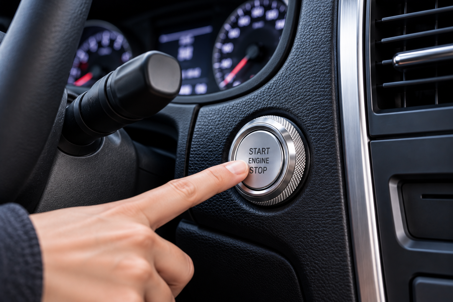
Inspecting the Existing Ignition and Immobilizer System
With trim removed, the first job was documentation. The owner identified constant power, ignition and starter behavior with a meter and compared those readings with available service information.
The vehicle also had a factory immobilizer, so the original key authorization still mattered. That prevented the common mistake of assuming a new button would bypass security.
The owner labeled each verified wire before making any splice.
Safety warning: Disconnect the 12V battery before modifying power wiring. Do not probe or modify SRS/airbag circuits. Keep added wiring fused, preserve neutral-safety or clutch interlocks, and never test-start an engine in an enclosed garage.
Finding a Practical Mounting Location and Routing the Harness
The first attractive location was rejected because an HVAC duct sat directly behind it. A second flat panel provided enough rear clearance and kept the button away from the airbag area and steering-column movement.
The panel was removed, measured and drilled on the bench. After deburring the opening, the switch was test-fitted before any wiring was routed.
The harness followed an existing loom where practical, with abrasion protection and a service loop behind the removable panel.
A simple verification routine
- Confirm battery and ground condition.
- Identify each circuit with documentation and a meter.
- Check relay and fuse requirements.
- Make temporary protected connections for testing.
- Verify operation before final trim assembly.
.jpeg)
Wiring, Testing and Fixing Problems Found During Installation
The starter-control path was handled through the appropriate relay rather than loading the dashboard button unnecessarily. Added power was fused and every splice was insulated and strain-relieved.
On the first test, the relay clicked but the starter did not crank. Voltage testing found excessive drop at an old vehicle-side connector, not a failed new switch. Repairing that connection restored a clean crank signal.
The engine then cranked but security authorization still depended on the original immobilizer arrangement, exactly as expected.
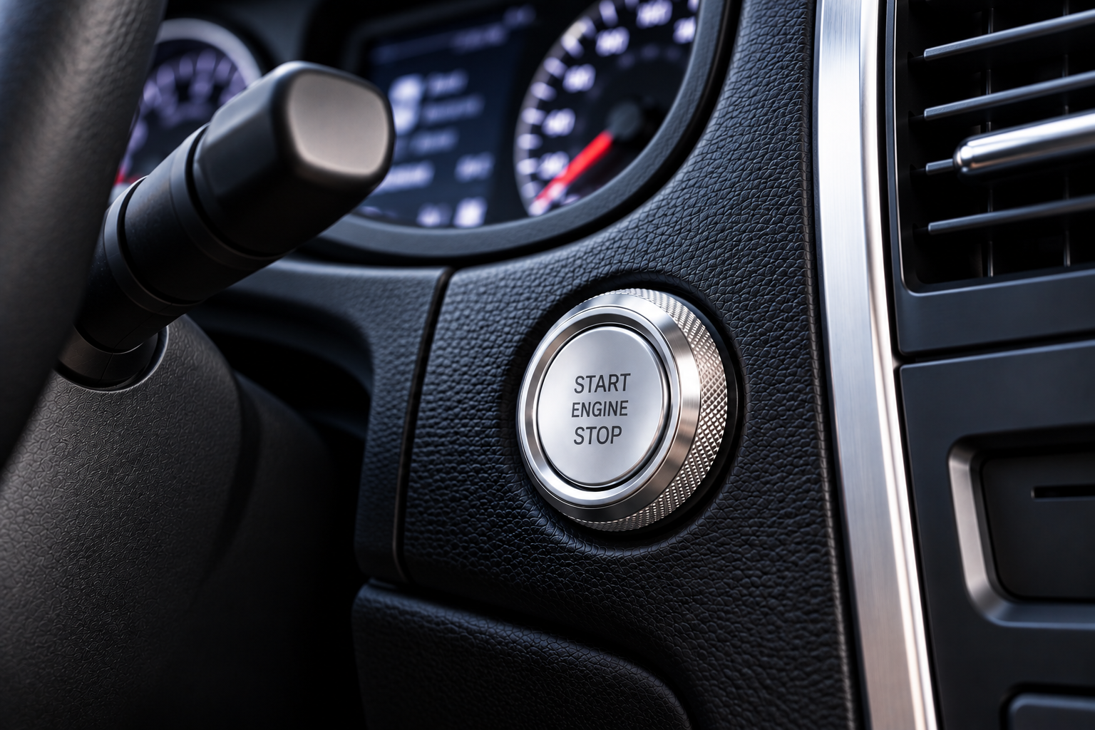
What the Owner Would Do Differently on the Next Installation
The biggest lesson was to inspect rear panel clearance before choosing a visible location. The second was to measure voltage under load rather than relying on continuity alone.
The owner would also label the harness earlier and photograph the original wiring before disconnecting anything. Those small steps make later service much easier.
A push-button project goes well when it is treated as electrical diagnosis first and cosmetic modification second.
Diagnostic Notes for Older 12V Vehicles
Older vehicles often carry evidence of previous electrical work. Before blaming a new component, inspect aftermarket alarms, remote starters, trailer wiring, audio feeds and old splices near the ignition harness. A connection that looks acceptable at rest can develop enough resistance under load to prevent a relay or starter solenoid from operating correctly.
Voltage-drop testing is especially useful. Measure across a connection while the circuit is operating; a large drop points to resistance in that path. This is more informative than a simple continuity beep, because continuity uses very little current and can make a weak connection appear healthy.
If the starter cranks but the engine does not run, separate the crank problem from the run problem. Check the security indicator, scan for immobilizer or engine-management faults when appropriate, and verify that required ignition feeds remain powered during crank. PATS, Passlock, SKIM, NATS and other immobilizer systems can stop engine operation even when the starter button and relay are functioning normally.
Do not defeat a safety or security circuit just to complete a test. The goal is to understand the original system and integrate the new control without creating an unintended start condition.
Practical Checklist Before You Finish
- No exposed copper or unsupported splices.
- Added power feeds are fused correctly.
- Harness cannot contact pedals, steering parts, sharp edges or hot surfaces.
- Starter disengages immediately after the crank command.
- Factory security and safety interlocks still operate as intended.
- No connector or relay becomes abnormally hot after repeated starts.
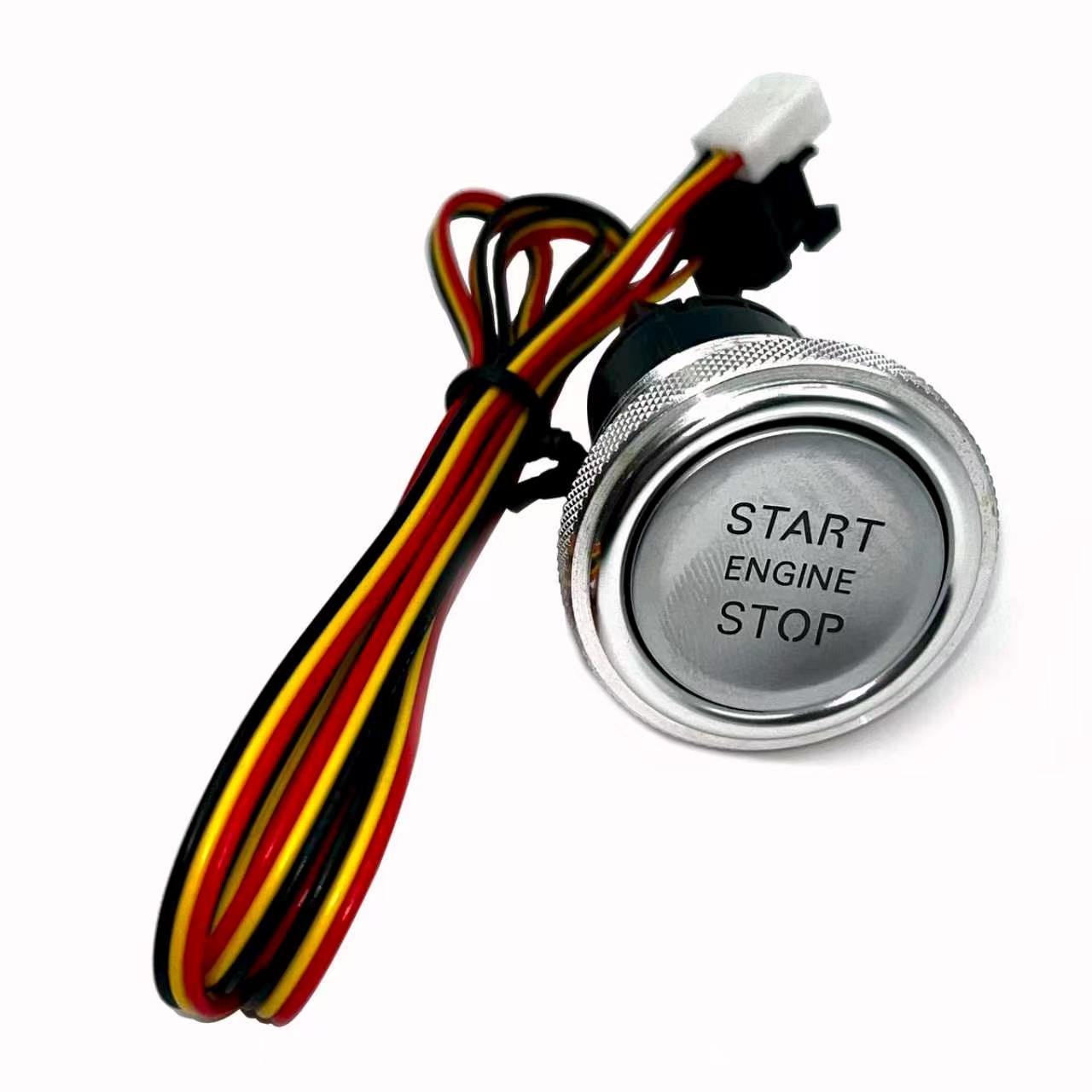
Need a Standalone 12V Start Button?
View the EFHIPS chrome metal START ENGINE STOP switch and its pre-wired harness.
View 12V Push Button Switch →Check vehicle wiring, mounting space and immobilizer requirements before installation.