Meta description: Install a 12V push button start switch safely with practical steps for mounting, circuit identification, relay use, testing, and final dashboard assembly.
Suggested URL slug: how-to-install-12v-push-button-start-switch
How to Install a 12V Push Button Start Switch: Step-by-Step Wiring and Mounting Guide
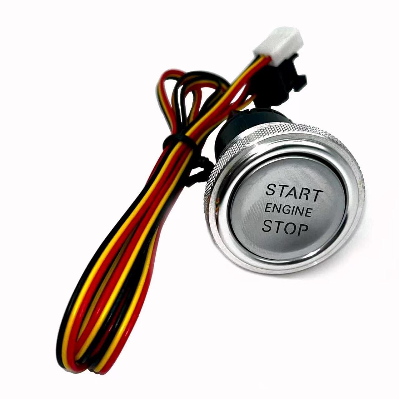
If you are working with a 12V push button start switch, the useful questions are electrical: what circuit are you controlling, how is it protected, and what factory systems still need to remain active? This guide focuses on those practical checks rather than treating a universal switch as a plug-and-play promise.
What You Need Before Starting the Installation
A clean installation starts before the first trim panel comes off. Confirm the vehicle is a 12V negative-ground system, obtain reliable wiring information, and decide whether the new button is replacing only a starter control or changing part of the ignition-switch logic.
Use a digital multimeter, trim tools, insulated crimping tools, suitable terminals, heat-shrink, fuse protection, and a relay when the controlled circuit requires one. Never size a wire or relay from appearance alone; use the actual circuit load and vehicle service information.
On 1990s–2010s vehicles, check for PATS, Passlock, SKIM, NATS, or another immobilizer before you cut anything. A button can command a starter circuit, but it does not automatically satisfy a transponder or security module.
- Verify the vehicle or equipment is a 12V DC application.
- Identify the exact circuit before connecting the harness.
- Check mounting depth as well as visible panel diameter.
- Keep the installation serviceable for future diagnosis.
Choosing and Preparing the Dashboard Mounting Location
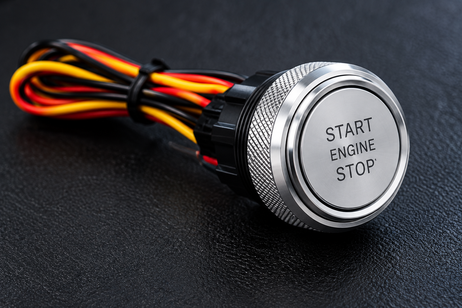
Pick a location you can reach naturally without placing the button near an airbag seam, steering-column movement, pedals, or a knee-impact area. Measure both the visible panel and the depth behind it; ducts, brackets, modules, and harnesses often occupy the space you cannot see.
Remove the panel before drilling whenever possible. Inspect both sides, mark the center, use the correct hole saw or step bit for the actual switch body, deburr the opening, and test-fit the threaded body before routing wires.
A loose hole creates a button that rotates every time it is pressed. A hole that is too tight can damage the finish or switch body, so work up to the final diameter rather than forcing the switch through the panel.
Safety warning: Disconnect the 12V battery before modifying power wiring. Do not probe or modify SRS/airbag circuits. Keep added wiring fused, preserve neutral-safety or clutch interlocks, and never test-start an engine in an enclosed garage.
Identifying 12V Power, ACC, Ignition and Starter Circuits
Do not match the EFHIPS harness to vehicle wiring by color alone. Verify constant power, ACC, ignition and crank behavior with a multimeter while moving the original key through OFF, ACC, ON and START.
Constant power remains near battery voltage in every key position. ACC normally appears in ACC and ON but may drop during crank. Primary ignition normally remains powered in ON and START. A starter trigger should appear only while the key is held in START. Some vehicles have IGN1/IGN2 or more than one accessory feed.
Write the readings down. If a wire behaves differently from what the diagram predicts, stop and resolve that difference before connecting the new switch.
A simple verification routine
- Confirm battery and ground condition.
- Identify each circuit with documentation and a meter.
- Check relay and fuse requirements.
- Make temporary protected connections for testing.
- Verify operation before final trim assembly.
.jpeg)
Connecting and Testing the Push Button Wiring Harness
Connect only after every vehicle-side circuit has been positively identified. Use secure crimped or soldered connections as appropriate for the installation, insulate exposed conductors, provide strain relief, and keep the harness away from sharp metal, heater ducts, pedals and steering components.
If the starter trigger requires more current than the switch/control circuit should carry, use an appropriately rated relay. The button then controls the relay coil while the relay contacts handle the starter-control load. Fuse any added constant-power feed close to its source.
Reconnect power only when loose conductors are insulated. Test ACC, ignition and crank functions in a controlled sequence rather than immediately trying a full start.
Final Installation Checks Before Reassembling the Dashboard
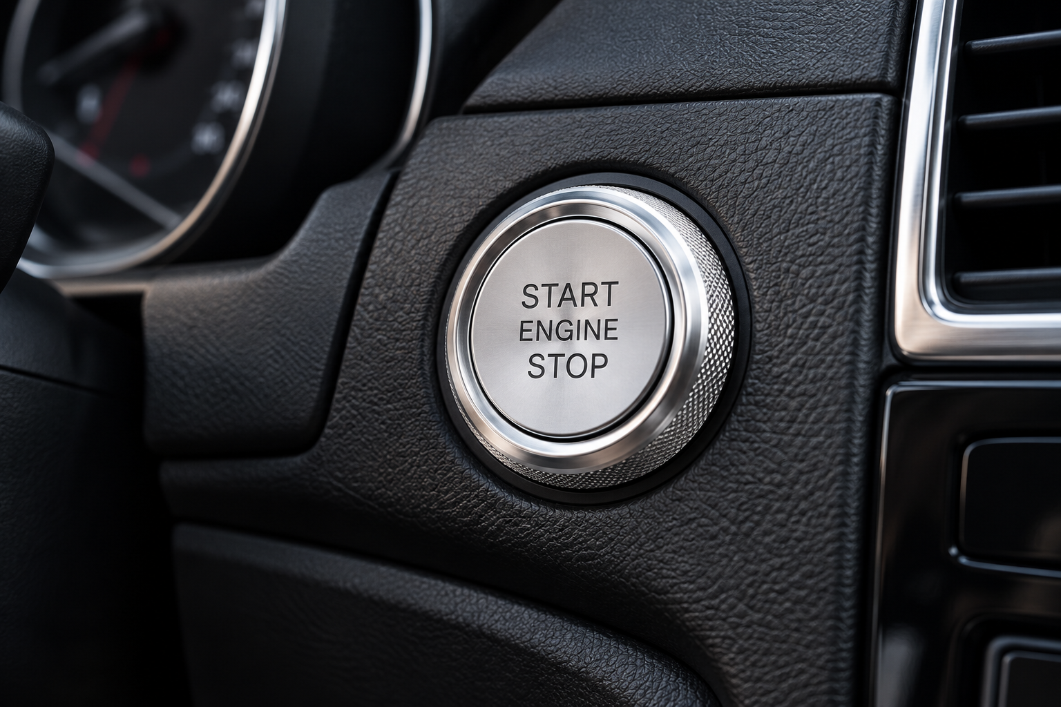
Verify that the starter disengages as soon as the start command is released and that no ignition or accessory circuit remains in an unintended state. Start the engine several times, then check the harness and relay for abnormal heat.
Watch the factory security indicator. Crank-with-no-start, start-and-stall, or a flashing security lamp can point to an immobilizer issue rather than a bad push button.
Finally secure the harness, reinstall trim without pinching wires, and confirm steering, pedals, HVAC controls and nearby switches move freely.
Diagnostic Notes for Older 12V Vehicles
Older vehicles often carry evidence of previous electrical work. Before blaming a new component, inspect aftermarket alarms, remote starters, trailer wiring, audio feeds and old splices near the ignition harness. A connection that looks acceptable at rest can develop enough resistance under load to prevent a relay or starter solenoid from operating correctly.
Voltage-drop testing is especially useful. Measure across a connection while the circuit is operating; a large drop points to resistance in that path. This is more informative than a simple continuity beep, because continuity uses very little current and can make a weak connection appear healthy.
If the starter cranks but the engine does not run, separate the crank problem from the run problem. Check the security indicator, scan for immobilizer or engine-management faults when appropriate, and verify that required ignition feeds remain powered during crank. PATS, Passlock, SKIM, NATS and other immobilizer systems can stop engine operation even when the starter button and relay are functioning normally.
Do not defeat a safety or security circuit just to complete a test. The goal is to understand the original system and integrate the new control without creating an unintended start condition.
Practical Checklist Before You Finish
- No exposed copper or unsupported splices.
- Added power feeds are fused correctly.
- Harness cannot contact pedals, steering parts, sharp edges or hot surfaces.
- Starter disengages immediately after the crank command.
- Factory security and safety interlocks still operate as intended.
- No connector or relay becomes abnormally hot after repeated starts.
.jpeg)
Need a Standalone 12V Start Button?
View the EFHIPS chrome metal START ENGINE STOP switch and its pre-wired harness.
View 12V Push Button Switch →Check vehicle wiring, mounting space and immobilizer requirements before installation.